B4M2: DIP24 W0.7" by-passable ¼" IO buffers
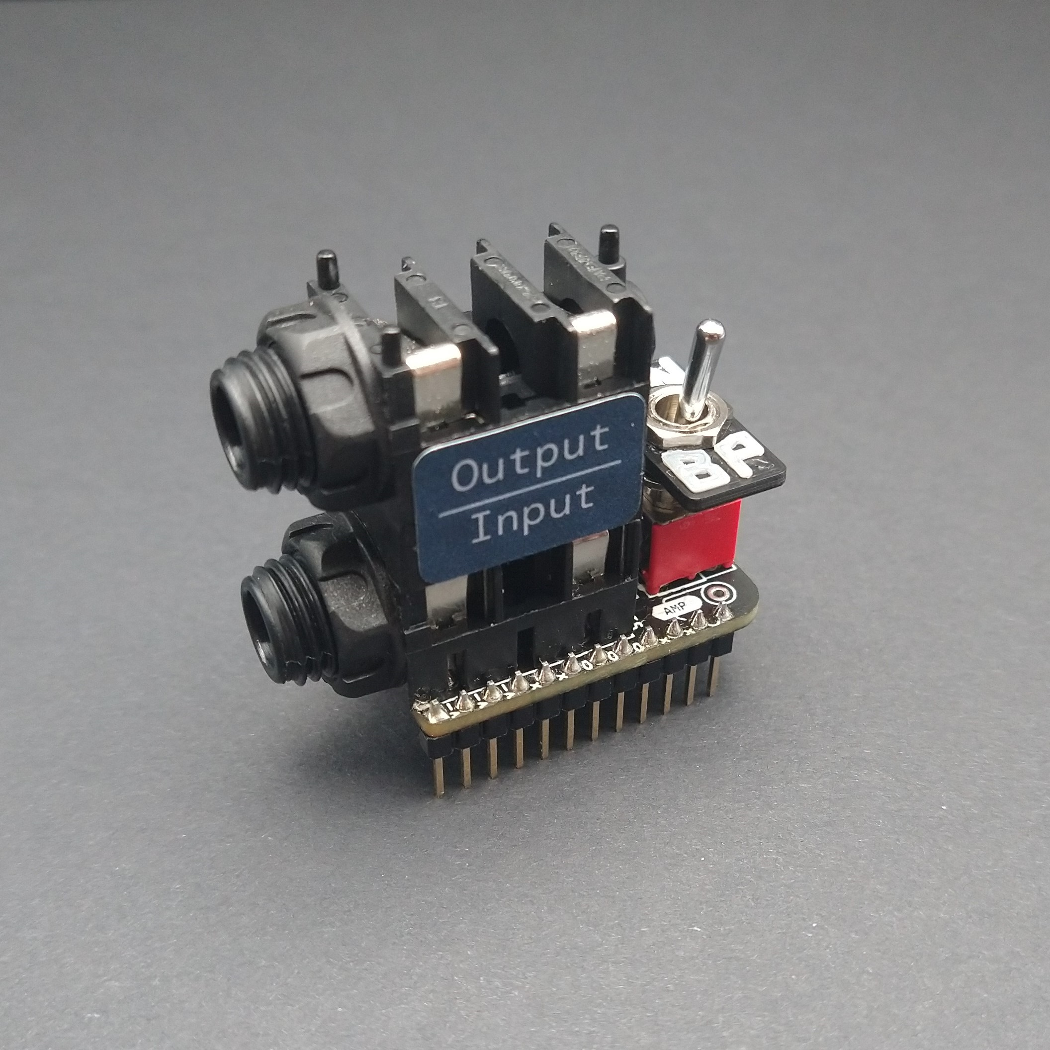
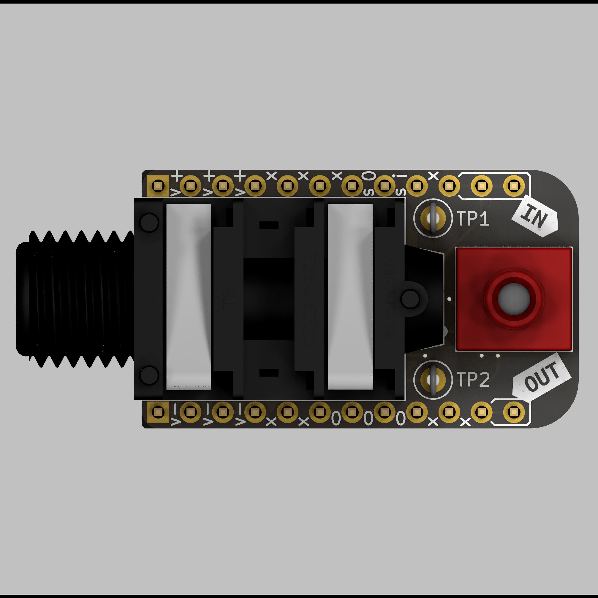
This is a by-passable input and output buffer module for convenient breadboard prototyping. It includes a compact stacked pair of ¼" jacks and can be (true) bypassed with a toggle switch.
Price: £16 (PCB with SMT components installed, through hole components included), £25 (+ through hole components installed)
If you have any questions please feel free to contact me via enquiries@macalisterelectronics.com or via Twitter (@macco_electro).
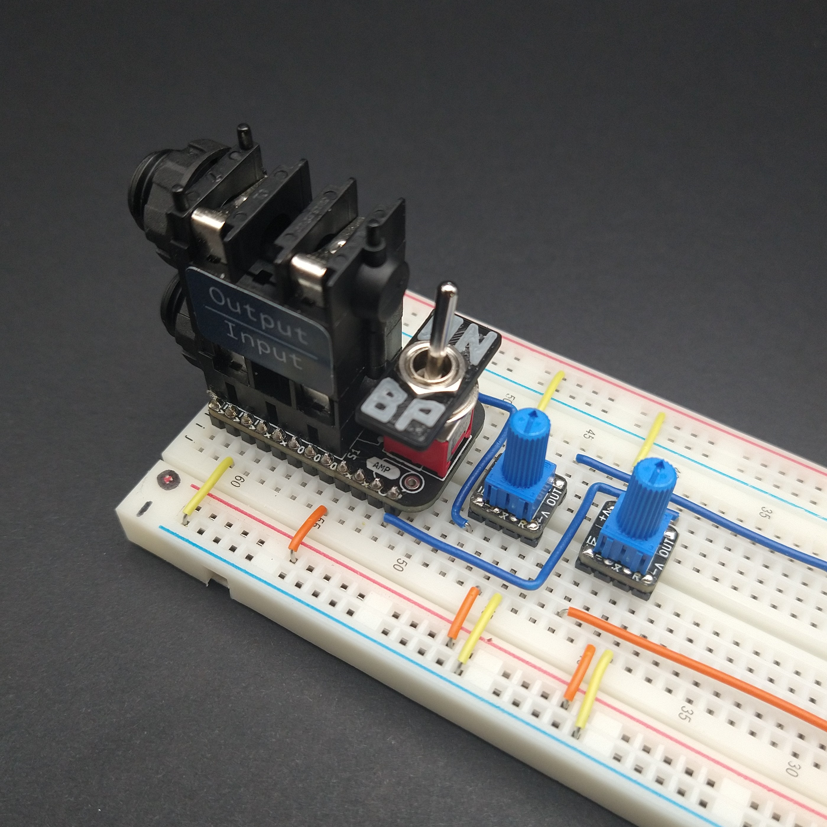
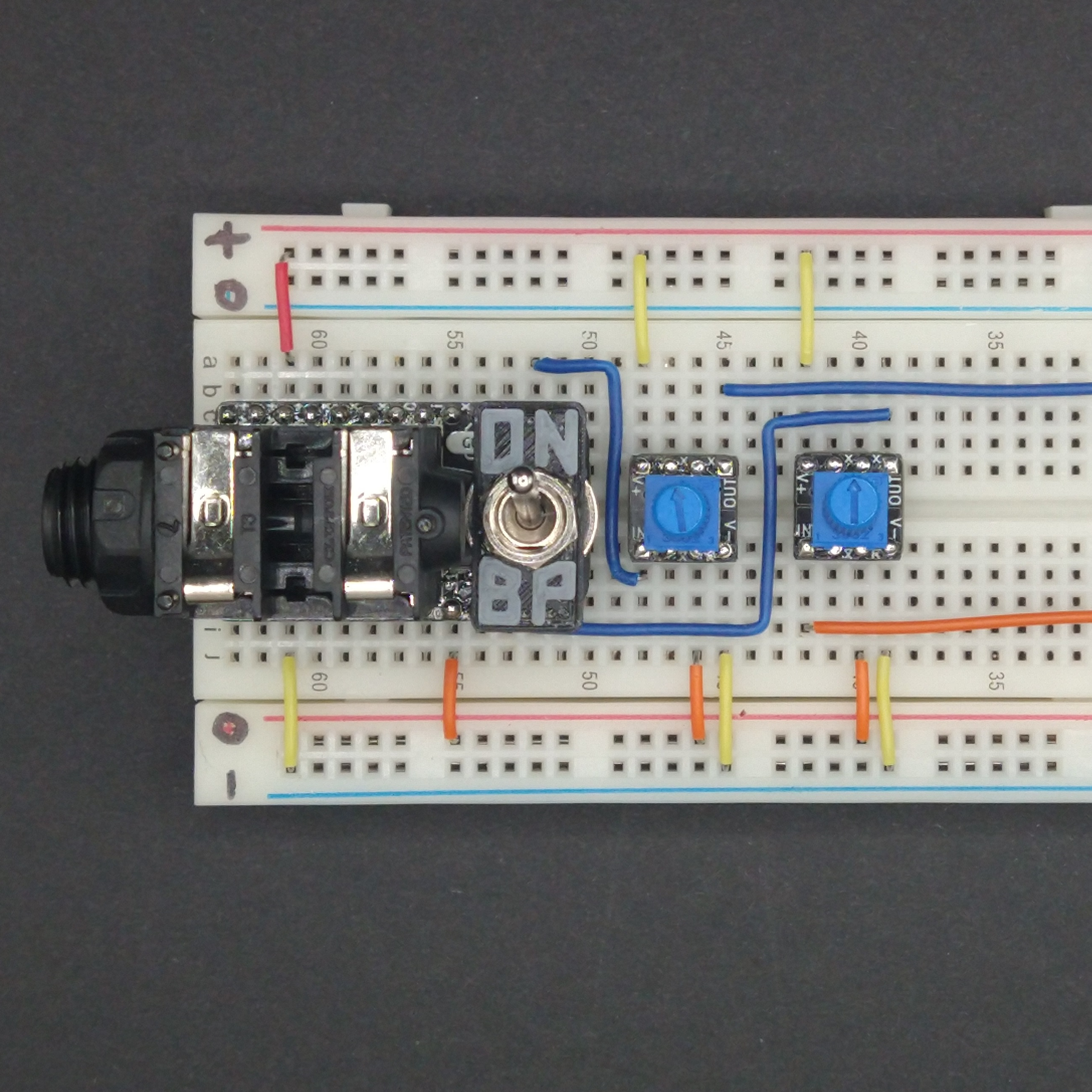
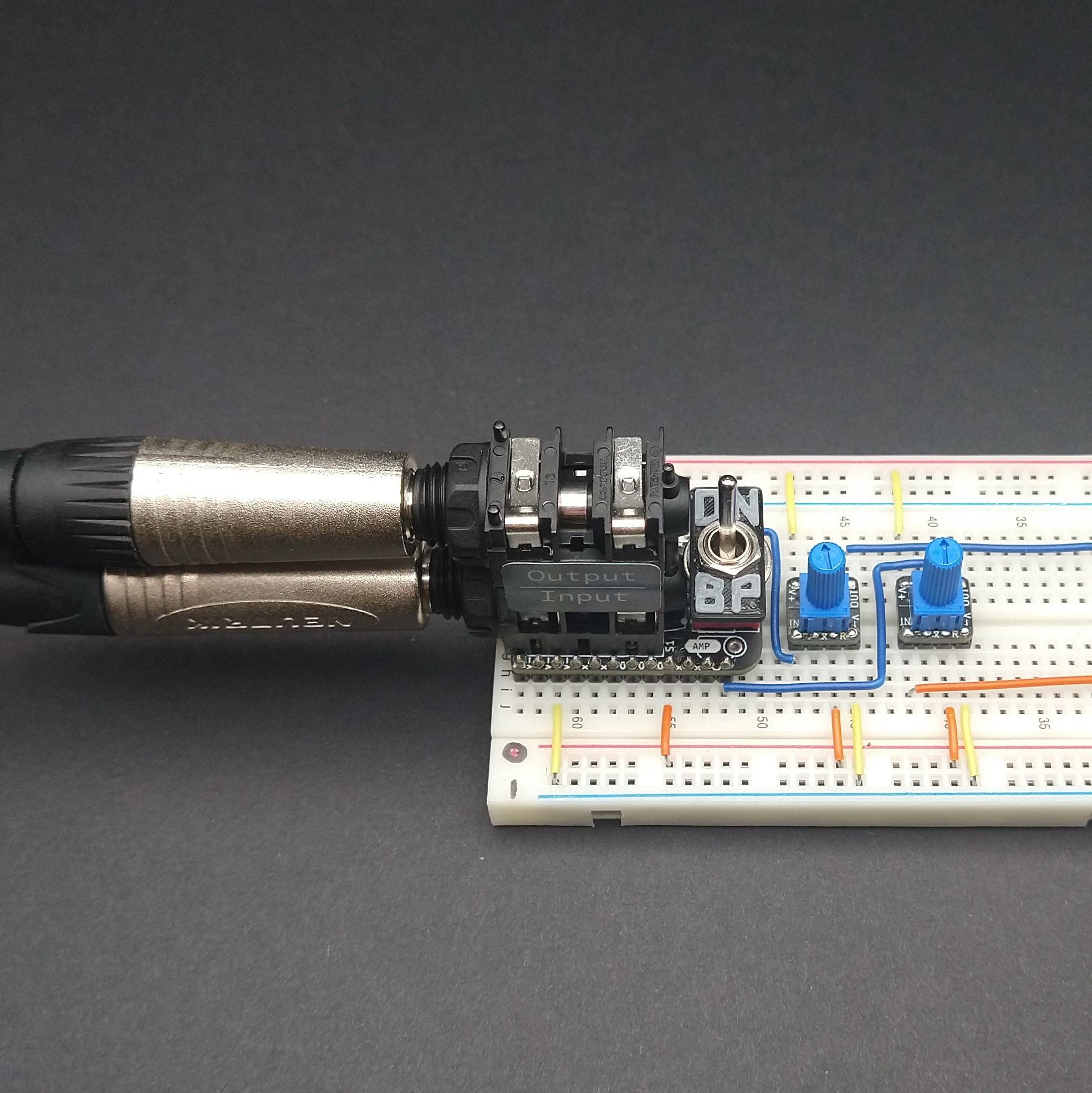
Gallery~
The images of this module on a breadboard depict an example application where the input and output signals are each connected to two separate B4M1 modules to allow their respective signal levels to be adjusted to suit the current signal levels.
n.b. The "ON/BP" toggle plate is not included but files to 3D print or otherwise make it are available here on Thingiverse
Detailed Description~
The goal for this module was to implement all the general I/O circuitry that is required when prototyping a guitar effect or similar analogue circuit on breadboard in a single small module. For me at least that means:
- Breaking out ¼" jacks for input and output (these do not usually fit into breadboards without a fight)
- Buffering the input signal so that the signal source isn't loaded (this can introduce unwanted low-pass filtering or more unpredictable but equally undesirable effects)
- Buffering the output signal so that the circuit under development isn't loaded
- Providing a bypass switch so that the circuit that is being developed can be switched in and out of the signal path easily
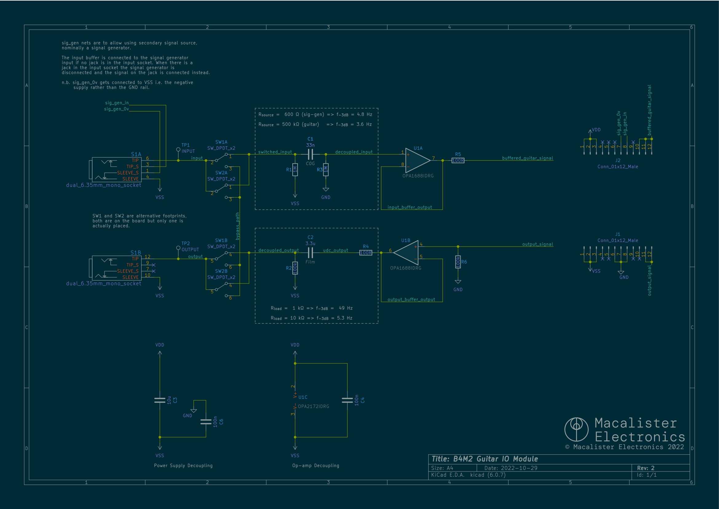
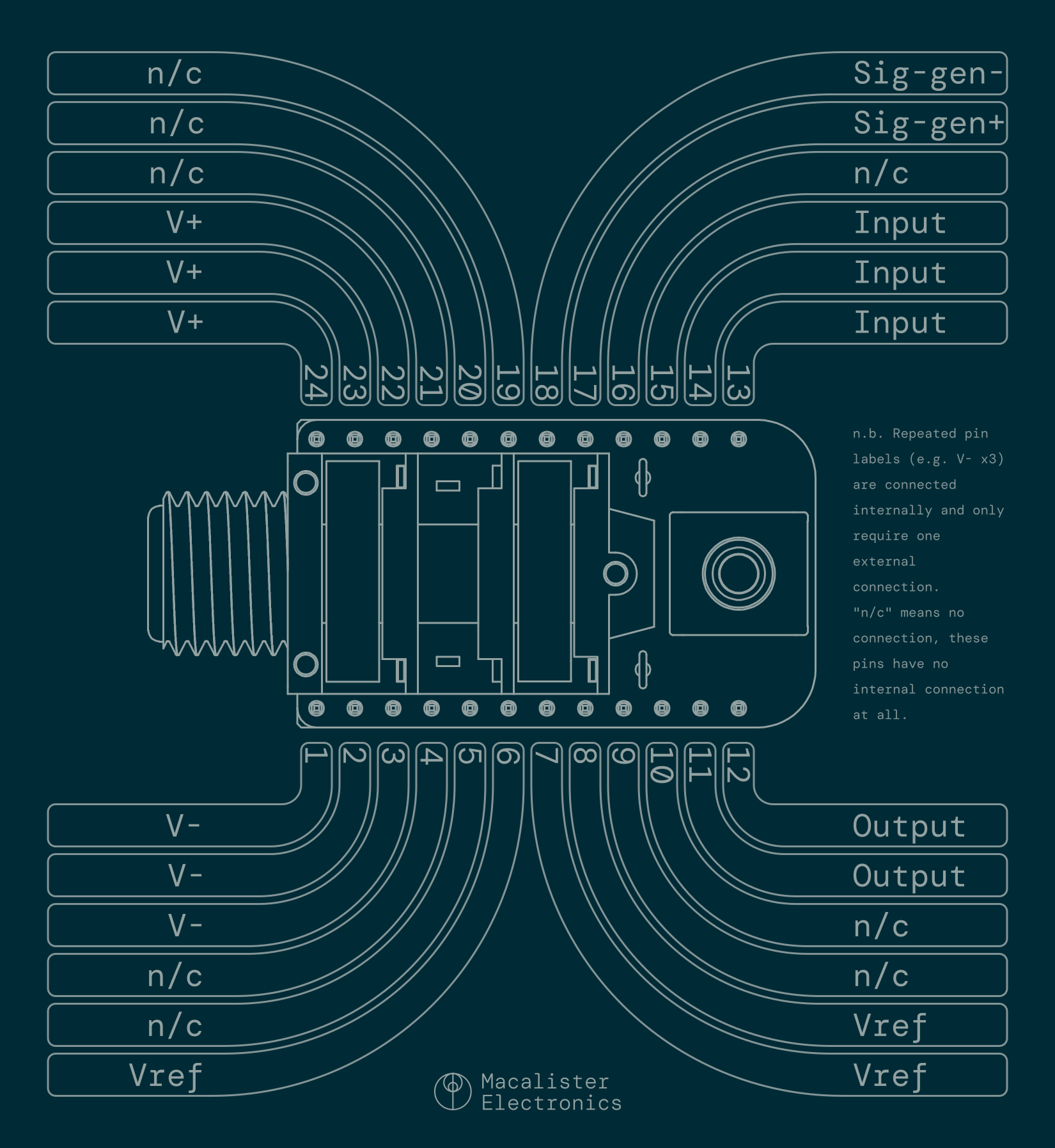
This module implements all of these features. As a bonus, because of the switching contacts built into standard jacks the input signal can automatically switch between two sources. When there is no plug in the input jack the input is instead taken from Pin 16 (Sig-gen+), when there is a plug in the input jack Pin 16 is disconnected and the input is taken from this plug.
n.b. The reference voltages for both inputs and the output are internally connected to the V- supply.
The circuit details are shown below.
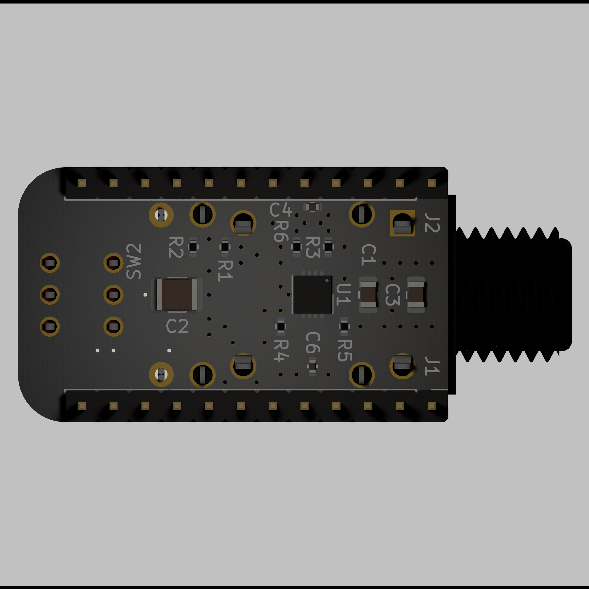
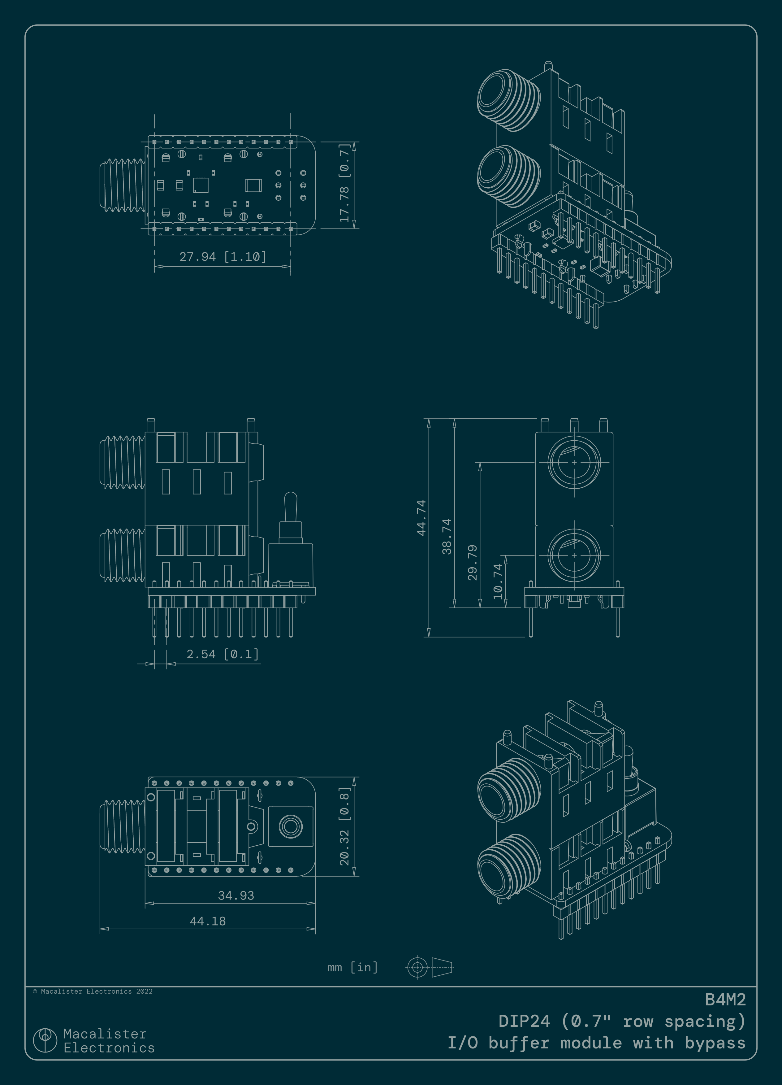
The module fits inside an extra-wide (0.7") DIP24 footprint which is mostly determined by the size of the jacks and the toggle switch. All of the other components are on the underside of the board so this layout is about as compact as is possible.
Details of the dimensions are shown below.
Pinout~
Assembly Notes~
When installing the toggle switch please note the correct orientation as shown in the images below.
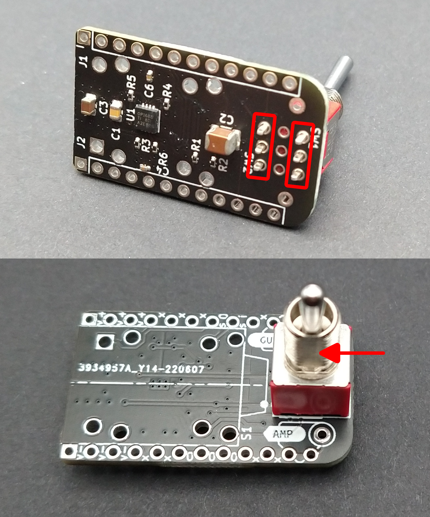
The switch will fit in rotated 90° from the correct position and this will not function correctly. There are two overlaid footprints on the board to allow installation of narrower toggle switches which is why there is an extra row of unused holes. When using the toggle switch style with an approximately square body it should be installed with the pins parallel to the short edge of the board.
The toggle plate design that is available on on Thingiverse requires that the switch be installed with the flat on the thread on "amp" side of the board - as shown in the second image. If you want to use a different toggle plate or none at all, the switch can be rotated 180° and it will still work correctly.
I find that it is generally easier to install the switch first, then the socket and the headers last. This will depend a bit on your soldering equipment but once the headers are installed it can be difficult to get a nice fillet on the pins of the socket due to the limited access.
Specification~
- Dimensions
- Width : 28.0 mm
- Depth : 17.8 mm
- Total Height : 44.7 mm
- Height Above PCB : 38.7 mm
- Weight : 20 g
- -3dB Bandwidth : 5 Hz to >100 kHz
- Port impedances (when enabled, true bypass otherwise)
- Input : 500 kΩ
- Output : 100 Ω
- Input signal range
- Upper limit: V+ + 0.5 V
- Lower limit: V- - 0.5 V
- Power supply
- Required supplies : V+, Vref, V-
- Recommended supply voltages : -4.5 V, 0 V, +4.5 V
- Reference voltage (Vref) : nominally (V+ - V-)/2
- Voltage range (V+ - V-) : 4.5 to 36 V
- Quiescent current : <4 mA