Damp Pulsatance
The Damp Pulsatance pedal is a resonant tunable low-pass filter. The filter cut-off can be controlled manually, by footpedal or using the integrated LFO. The LFO can be triggered by the input signal or left to free-run.
Final assembly and test is all in the UK. The PCBs are built and assembled in Europe. All other components are sourced from UK suppliers where possible.
Lead time is currently: 2 weeks.
Price: £360
If you have any questions please feel free to contact me via damp_pulsatance@macalisterelectronics.com with Damp Pulsatance in the subject or via Twitter (@macco_electro).
Demonstration Video~
Gallery~
Sound Clips~
All of these clips were recorded with a Squier Strat and an old Vox Valvetronix amplifier. The amp was recorded through an SM57 and a Focusrite Scarlett 2i2.
This clip used an extra distortion effect between the guitar and the Damp Pulsatance.
This clip used an MXR Blue Box clone between the guitar and the Damp Pulsatance. The Blue Box is a fuzz and 2-octave down pedal. The clone was built from a Tonepad kit. I just played all of the strings open; this is a bit much for the Blue Box tracking so it ends up generating a lot of noise. The Wah-y fade out is achieved by setting the Centre Off control such that the filter has a fairly low cut-off frequency when the LFO is not running.
This clip used the same MXR Blue Box clone but this time it was used as intended, to create a single note bassline.
Detailed Description~
The filter section is an LM13700 tunable state-variable low-pass (almost directly as per the datasheet : "Voltage-Controlled State Variable Filter"). A resonance control has been added to the datasheet topology. When this is turned up the filter approximates an auto-wah. When it is really turned up, the filter and output stages clip with predictable results. The filter centre-frequency can be controlled manually, or via an expression pedal or via the triggered L.F.O. The filter's input signal is the one from the Input socket, and the envelope of that signal also triggers the L.F.O.
However, if the Sidechain Receive socket has something plugged into it, the envelope of that signal is instead used to trigger the L.F.O. The sidechain allows other effects to be added to guitar signal before the filter whilst still triggering the L.F.O. from a clean input signal in case the clean dynamics are preferred. The Sidechain Receive can of course also be used as a general-purpose trigger input and for example be fed from a drum track.
The L.F.O. frequency can also be controlled manually or via a expression pedal. The LFO output is a triangle wave with a shape control that allows it to be smoothly bent into both backwards- and forwards-leaning sawtooth waves. The LFO is triggered from the the built-in Envelope Detector.
The Threshold control for the Envelope Detector can be set to keep the LFO always triggered or always untriggered. The Release control determines how long the Envelope Detector takes to return to the off state.
The output stage allows between +3 and -∞ dB of gain. Because the resonance of the filter can get a bit silly, the output stage has clipping diodes both to keep the output levels reasonable and to allow a bit of post-distortion.
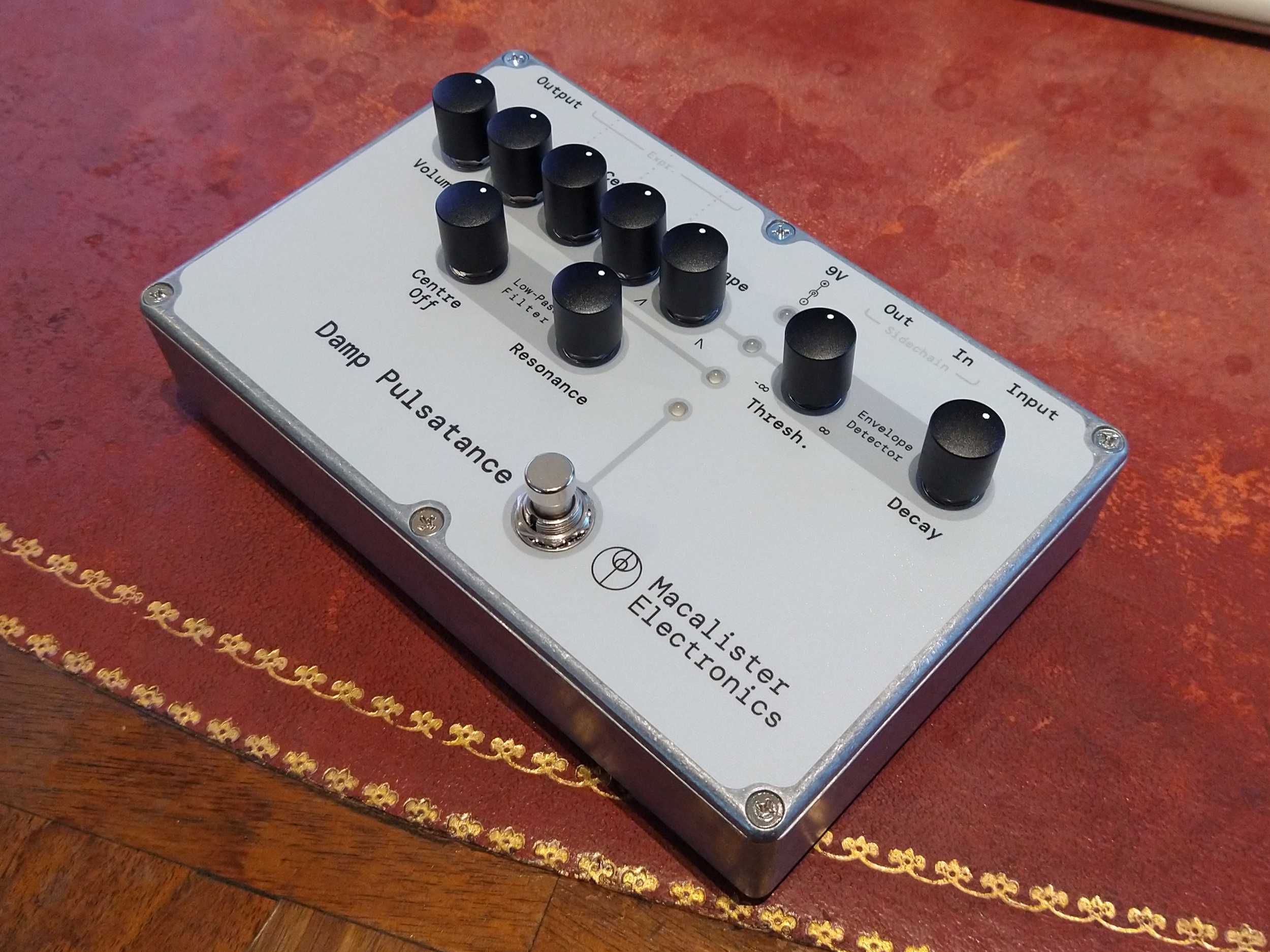
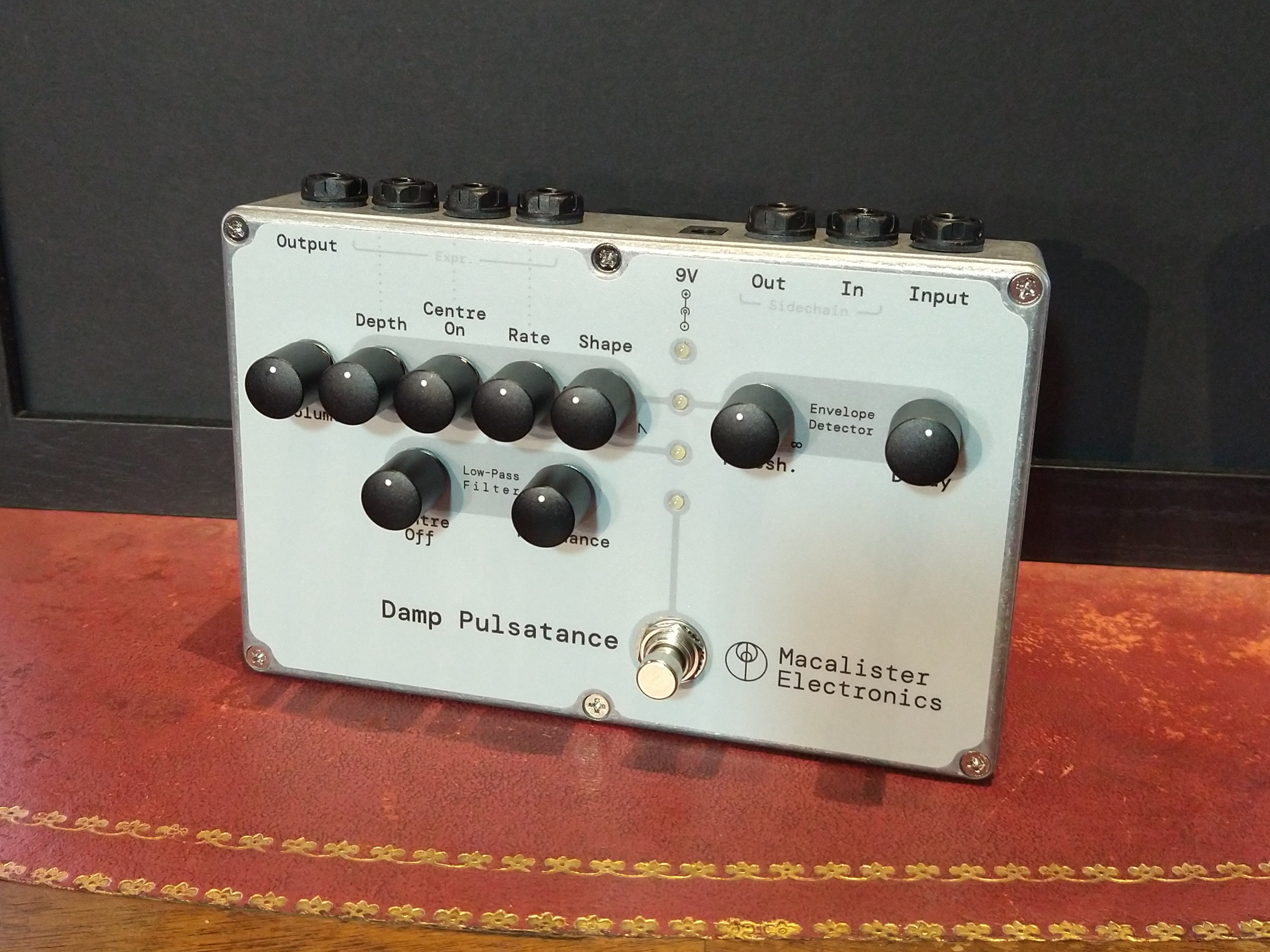
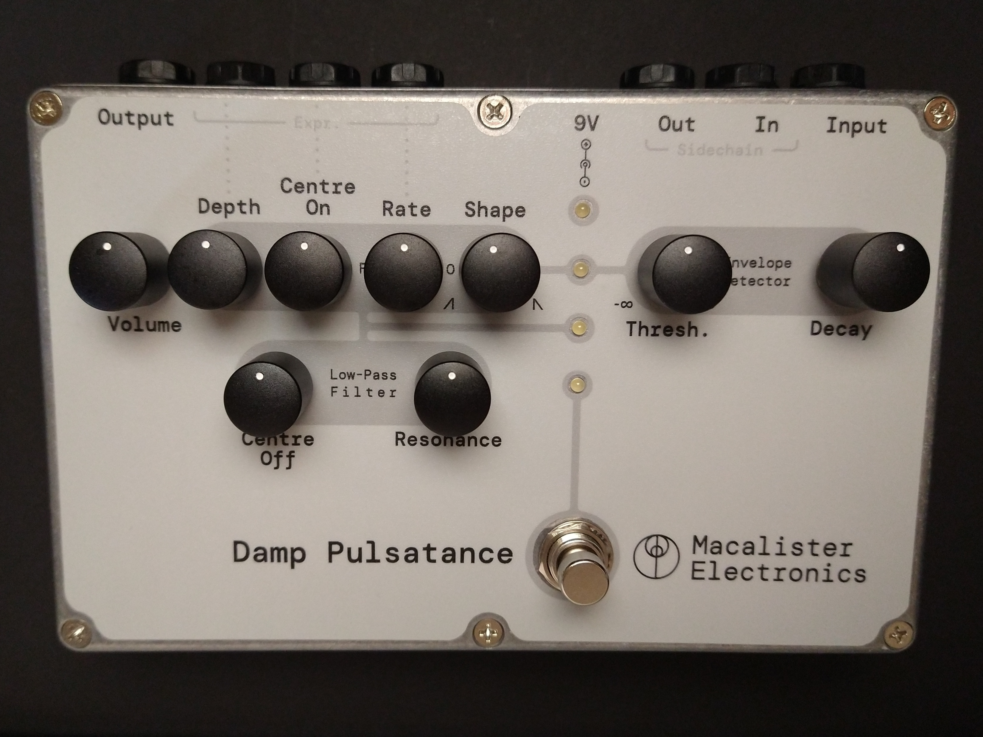
Legend for Controls and LEDs~
| LED | Purpose |
|---|---|
| Top | Power indicator |
| Bottom | Bypass indicator (off = bypassed) |
| Upper Middle | Envelope detector output state (on = signal detected) |
| Lower Middle | LFO output level / filter cut-off frequency (brighter = higher cut-off frequency) |
Italicised knobs also have expression pedal control
| Knob | Purpose |
|---|---|
| Envelope Detector | |
| Threshold | Signal level above which the envelope detector output is high. Clockwise for a higher level. Fully anti-clockwise will cause the output to stay high all the time and the L.F.O. to oscillate likewise. |
| Release | Time for the envelope detector output to return to low after the input signal level goes below the threshold. Clockwise for a longer time. |
| L.F.O. | |
| Shape | At 12 o'clock the LFO output will be a triangle wave. Fully anti-clockwise will make the L.F.O. output a sawtooth wave where the sloped edge is downward-going and vice versa for fully clockwise. |
| Frequency | Fully anti-clockwise will set the oscillator to approximately 0.2 Hz (G-7), fully clockwise will set the oscillator to approximately 130 Hz (C3). This range can be shifted up or down by changing a capacitor on the PCB. |
| Centre On | This adds a DC value to the oscillator output. This determines the frequency about which the V.C.F. cut-off is modulated. Turning this knob clockwise makes the filter more "open" i.e. the filter's cut-off frequency is will on average be higher. |
| Depth | The controls the oscillator output amplitude. This in turn controls how much the centre frequency of the V.C.F. is modulated. Turning this knob clockwise increases how much the V.C.F. centre-frequency is modulated. |
| Filter | |
| Centre Off | This does the same thing as the Centre On knob; however, the position of this knob sets the V.C.F. cut-off frequency when the L.F.O. is not triggered. The filter cut-off can be varied between 24 Hz (G0) and 2.4 KHz (D7). This range has been optimised for bass or sub-bass synth inputs, it can be shifted up relatively easily by adding two capacitors to the PCB. |
| Resonance | Turning the knob clockwise increases the filter's resonance, i.e. instead of being a simple low-pass filter it becomes a low-pass filter with a peak at the cut-off frequency. |
| Output Stage | |
| Level | Output stage gain, fully anti-clockwise mutes the output and fully clockwise sets the gain to about x2 but will be limited by clipping diodes. |
Specification~
- Dimensions
- Width : 188 mm
- Depth : 127 mm
- Height : 60 mm
- Weight : 700 g
- Expression pedal
- Resistance range : 1 Ω to 10 kΩ
- Connector : variable resistance between tip and ring on a TRS jack e.g. this M-audio one (others may work but that is one I have tested).
- Port impedances (when enabled, uses true bypass)
- Input : 680 kΩ
- Output : 100 Ω
- Power supply
- Voltage : 9 V
- Current : 50 mA
- Connector : 5.5 mm x 2.1 mm barrel jack, centre negative